Parts
Hardware Components
1
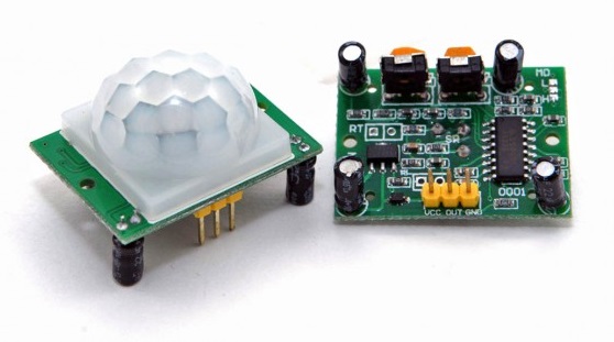
PIR Motion Sensor
This Module looks for motion and when sensing it, will send out a signal. This signal will turn on a switch to turn on the LED Strip.
2
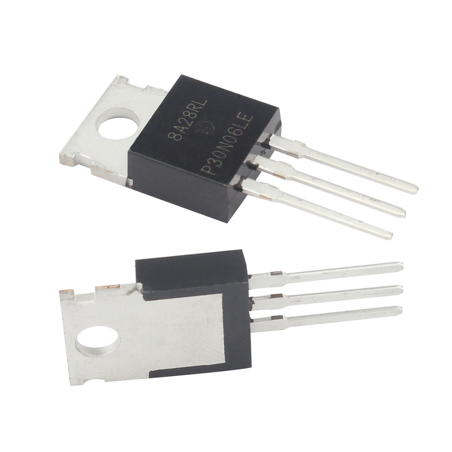
N-Channel MOSFET
The transistor is used as a switch to turn on and off the LEDs when receiving a signal from the Motion Sensor
3
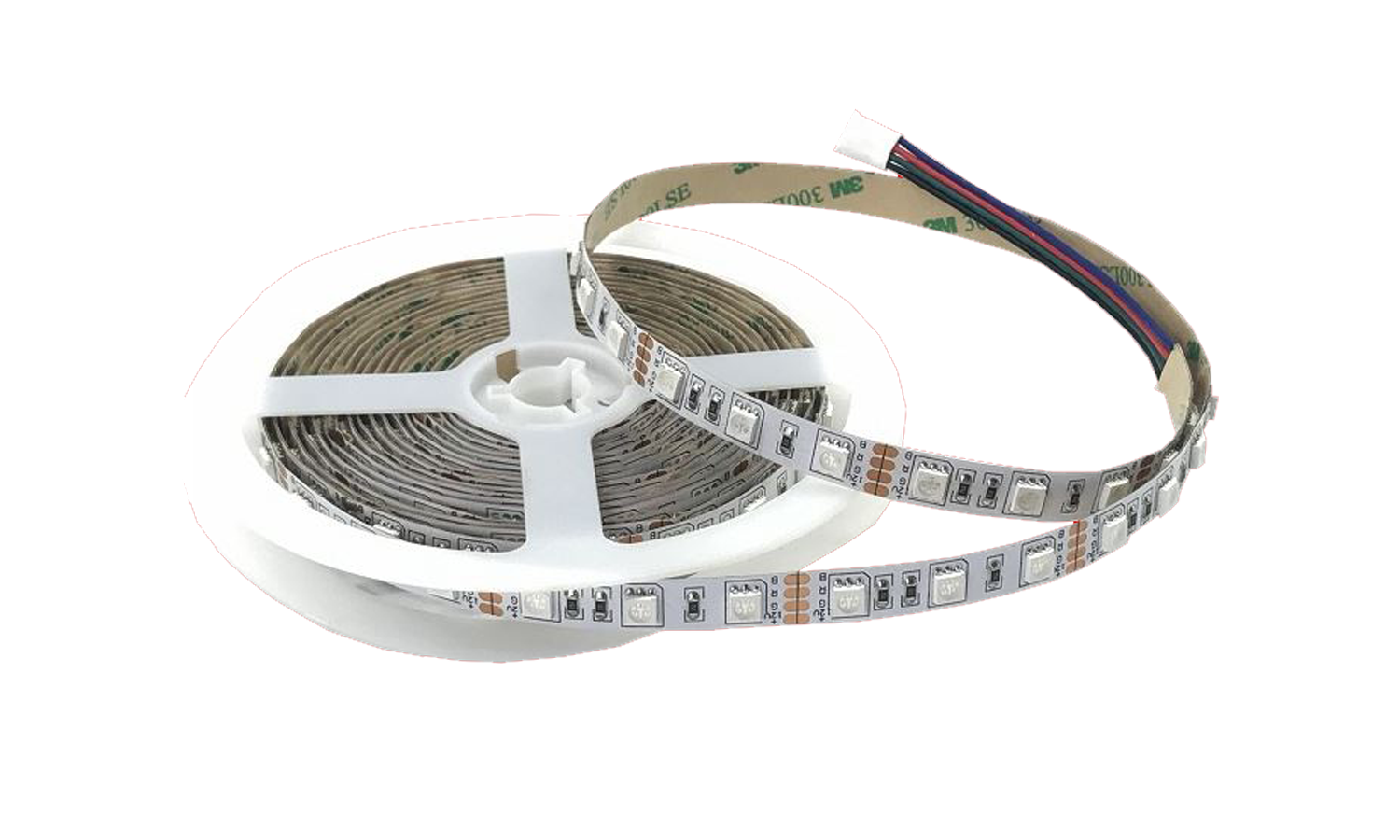
LED Strip
When the PIR module senses motion, it tells the MOSFET to send voltage to the LED strip to brighten underneath the bed.
4
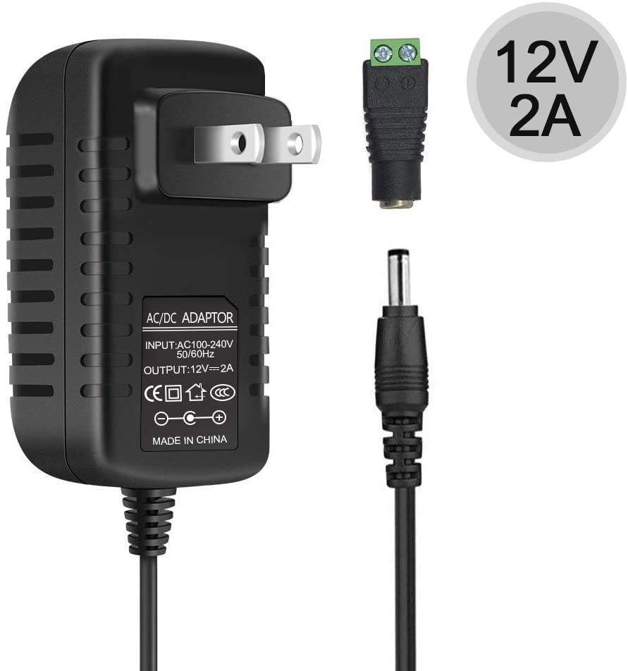
12V Power Supply
The power supply is used to power on the PIR Module and also will illuminate the LED strip when activated in the circuit.
Instructions
Instructions
1
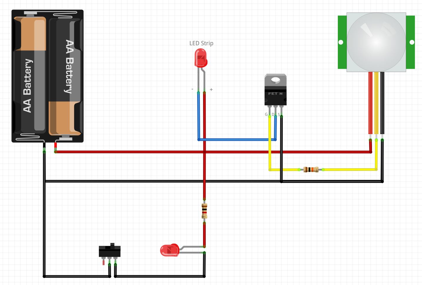
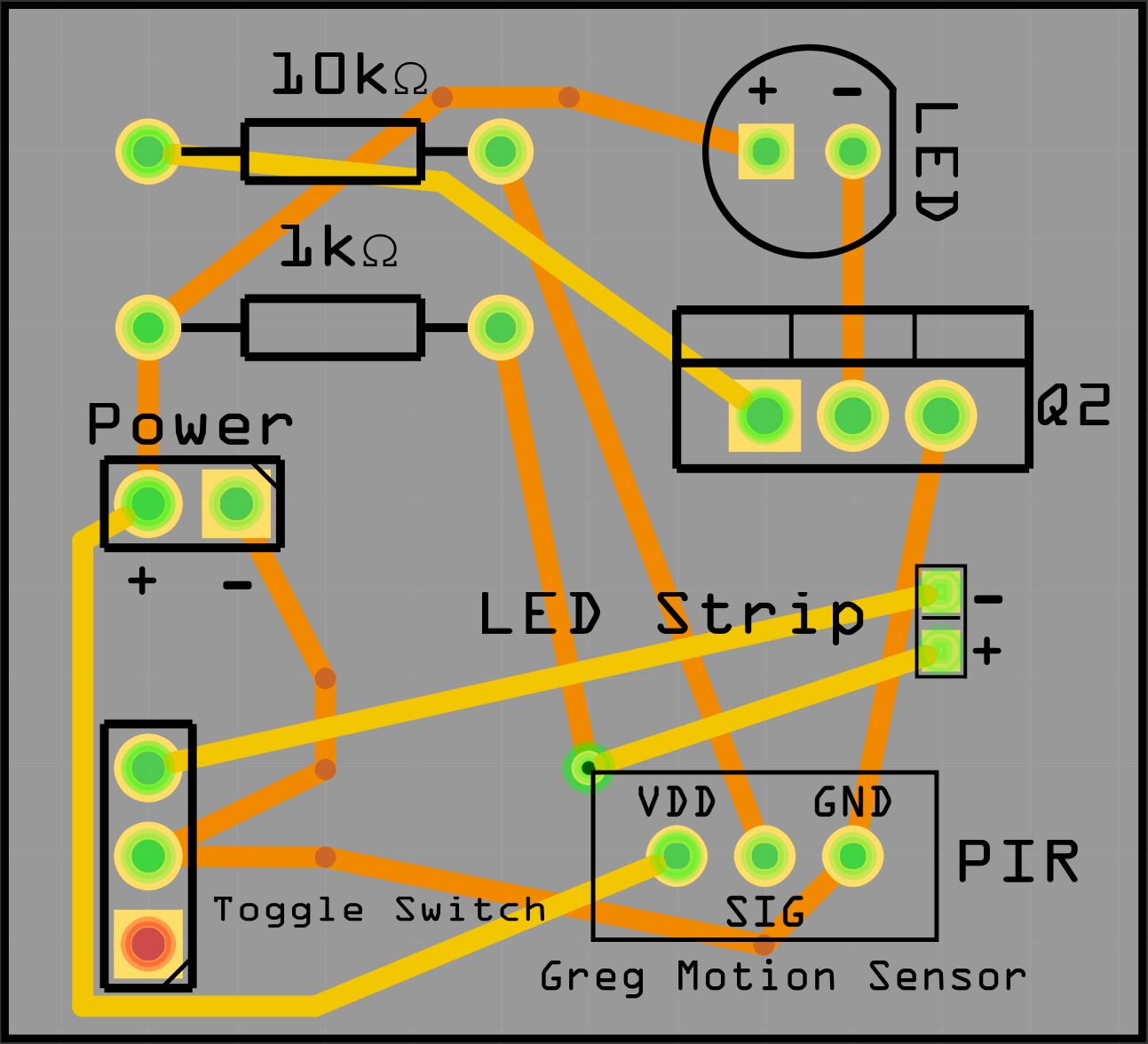
Setup Circuit based on Schematic
Using the Diagram, wire together the Motion Sensor to the MOSFET, LEDS and Power Supply. Supply can be a wall adapter (5VDC) or a battery pack. Click button for full image
2
3
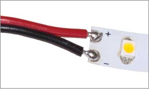
Connection to LED Strip
Make sure you supply the Red to (+) for positive voltage and the Black Wire to (-) for negative voltage.
4
Using a MOSFET
When the signal voltage is received at the Gate (G) from the Motion sensor, this allows voltage to flow between the Source (S) and Drain (D). This will turn on the LED Strip.